


CPO FIBER SHUFFLE & FLEXIBLE OPTICAL BACKPLANE
Why CPO Systems Need Flexible Optical Backplanes
High-density, passive fiber routing for the next generation of AI data-center switching.
AT A GLANCE
Co-packaged optics, or CPO, places optical engines close to the host ASIC on a shared high-performance substrate or package. This shortens the high-speed electrical path. But it creates a new physical challenge: routing a very large number of optical fibers through a crowded switch enclosure. An OPTICO Fiber Shuffle or flexible optical backplane solves this challenge with a predefined, factory-built passive fiber-routing map.
CPO Is Moving Optical Interconnect Closer to the ASIC
AI, cloud computing and high-performance computing are driving continuous growth in switch bandwidth, port density and computing scale. Conventional pluggable optics must carry high-speed electrical signals from the switch ASIC across the PCB and into an external module. At higher signaling rates, that electrical path becomes increasingly demanding in terms of loss, power and signal integrity.
CPO addresses this challenge by placing the optical engine in close proximity to the ASIC. The shorter electrical reach can reduce channel loss and impedance discontinuities, helping the system pursue higher bandwidth density, lower power and lower latency. However, the value of CPO also depends on whether the complete optical interconnect can be manufactured, routed and serviced reliably at scale.
CPO VALUE CHAIN
| Switch ASIC | → | Optical Engine | → | Fiber Shuffle / Flexible Optical Backplane |
The ASIC-to-optical-engine link is electrical. The Fiber Shuffle manages the optical fibers after the optical engine, routing them to the required interfaces inside the system.
The New Bottleneck: High-Density Optical Routing Inside the Switch
Moving the optical engine closer to the ASIC does not eliminate the optical routing task. It brings that task inside the switch. Depending on the port count, number of optical engines and plane architecture, a high-radix CPO system can require the coordinated routing of hundreds to more than one thousand fibers. There is no universal fixed fiber count per ASIC; the requirement is always architecture-specific.
|
01 / FIBER COUNT A dense CPO architecture must organize a large number of data fibers in a defined order while preserving the required channel mapping. |
02 / LIMITED SPACE Fibers must share a limited enclosure with the ASIC, optical engines, cooling hardware, power modules, control electronics and front-panel interfaces. |
03 / ELS ROUTING Where an external laser source is used, its separate laser-delivery path must coexist with data-fiber routing in the same compact system. |
Critical design principle: compact routing must still respect the specified minimum bend radius. The goal is not the smallest possible bend; it is controlled routing that avoids bend-induced insertion-loss risk while fitting the available mechanical space.
What Is a CPO Fiber Shuffle?
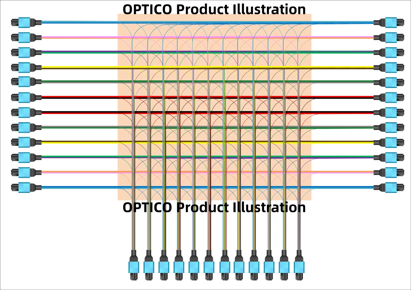
A CPO Fiber Shuffle is a customized passive optical interconnection assembly. It uses a confirmed routing matrix to distribute fibers from the optical engines to front-panel data interfaces, internal modules or other defined endpoints. In an external-laser architecture, it may also route the laser-delivery path to the optical engine.
It is not an optical switch, signal converter or amplifier. The Fiber Shuffle does not process the optical signal. Its function is to deliver the right fiber from the right source to the right destination in a compact, stable and repeatable physical format.
ILLUSTRATIVE OPTICAL PATHS
| DATA PATH | Optical Engine | → | Fiber Shuffle | → | Front-Panel Data Interfaces |
| LASER PATH | External Laser Source | → | Fiber Shuffle | → | Optical Engine |
Note: The laser path applies only when the selected CPO architecture uses an external laser source. PM fiber can be specified for this path when the design requires polarization stability.
How Flexible Optical Backplanes Create Value
|
01
|
Controlled Fiber Mapping and Optical ConsistencyA predefined routing map, controlled fiber placement and bend-aware path design help reduce the risk of inconsistent installation. The objective is to mitigate bend-induced insertion-loss variation and deliver repeatable factory-assembled optical paths. Insertion-loss and return-loss targets should be defined and verified at the assembly level. |
|
02
|
Flexible Thin-Film Structure for Complex RoutingFibers can be organized on or within a flexible protective film structure rather than managed as loose bundles. The substrate size, shape, fiber count, routing map, connector type, positioning features and termination format can be customized for the actual CPO package and enclosure. |
|
03
|
Modular Installation and Service StrategyA flexible backplane can be integrated into a module or shuffle cassette with predefined branches for individual optical engines. This organized structure can simplify installation, isolate routing paths and support service access without disturbing the complete internal fiber bundle. Equal-length or controlled-length branches can be designed when required by the system architecture. |
|
04
|
Scalable Manufacturing and RepeatabilityPre-terminated, factory-tested assemblies reduce on-site fiber handling and help standardize production quality. Automated or controlled fiber-laying processes can support repeatable routing for large-scale CPO and AI data-center deployments. |
A Density Reference: Why Form Factor Matters
Flexible optical backplanes are designed to use equipment space more efficiently than conventional loose fiber distribution. The comparison below is an illustrative capacity reference based on a high-density MT-connector design, not a universal product specification.
|
CONVENTIONAL REFERENCE 24 fibers / 1U A conventional fiber distribution arrangement may support 24 fiber connections per 1U. |
FLEXIBLE BACKPLANE REFERENCE 600 fibers / 1U For example, 12 high-density MT interfaces with 50 fibers each can support 600 fiber connections in 1U. |
Illustrative 40U comparison: 24 fibers × 40U = 960 fiber connections, while 600 fibers × 40U = 24,000 fiber connections. This shows why flexible optical backplanes can significantly improve density where the connector system, enclosure design and routing architecture support it.
Design Inputs That Must Be Confirmed Before Production
For a Fiber Shuffle, the routing matrix is the product. A complete design review should define both the optical mapping and the mechanical installation conditions.
|
01
|
Endpoint mapping Every source port, destination port, plane allocation and branch relationship. |
|
02
|
Fiber and interface specification Single-mode or PM fiber, connector type, fiber count, polarity, channel sequence and termination format. |
|
03
|
Mechanical envelope Base size, shape, mounting position, connector exit direction, available space, bend-radius limit and strain-relief requirements. |
|
04
|
Optical acceptance criteria Insertion loss, return loss where applicable, continuity, end-face quality, labeling and traceability requirements. |
OPTICO CUSTOM PASSIVE INTERCONNECT SOLUTIONS
From Fiber Mapping to Factory-Tested CPO Integration
OPTICO develops customized CPO Fiber Shuffle and flexible optical backplane assemblies around the confirmed system architecture. The solution can be designed for custom substrate dimensions and shape, fiber mapping, connector interfaces, positioning features and mechanical integration. MPO/MTP, SN-MT and MMC interfaces can be considered according to the final application requirement. Because the internal mapping is fixed after production, validating the design before fabrication is essential to reliable first-time integration.