


Shenzhen Optico Communication Co., Ltd. is one of the most credible manufacturers and suppliers of data center shuffling solution in China. Please feel free to wholesale high quality customized products at competitive price form our factory. If you have any enquiry about free sample, please feel free to email us.
Product Profile
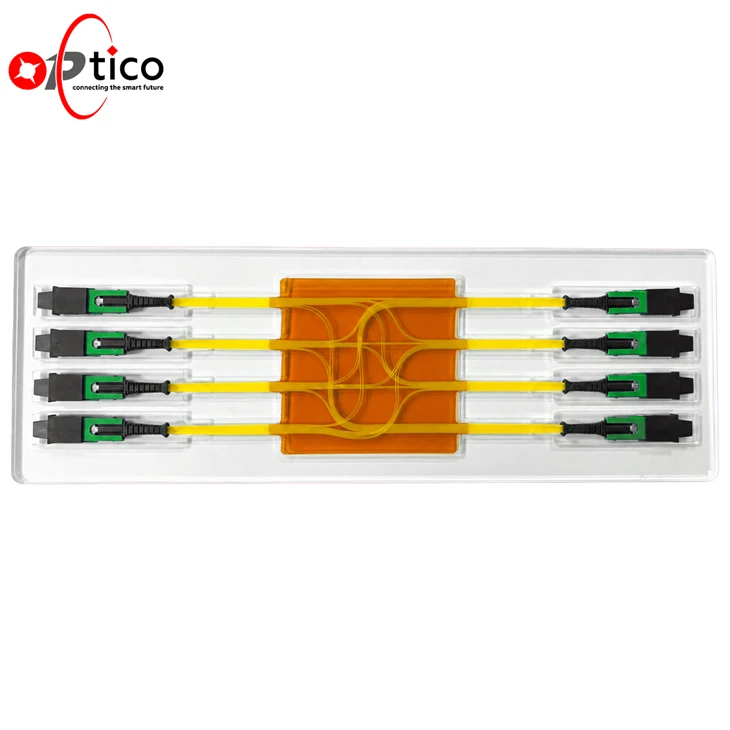
Data Center Shuffling Solution: Our Data Center Shuffling Solution is available in 2×2, 4×4 and 8×8 configurations, providing customized, high-density optical lane routing within a compact structure. Each assembly redistributes fiber lanes across multiple MTP®/MPO interfaces according to the required port mapping and network topology, helping simplify cable management, reduce connection complexity and optimize space utilization in high-density optical interconnect systems.
Product Specifications
| Physical Properties | Parameter | ||
| Shuffling Configuration | 2×2, 4×4, 8×8 or customized | ||
| Connector Interface | MTP / MPO / SN-MT / MMC | ||
| Connector Fiber Count | 8F, 12F, 16F, 24F or customized | ||
| Total Fiber Count | Determined by connector configuration | ||
| Fiber Mode | Single-mode or multimode | ||
| Fiber Type | G.657.A1 / G.657.A2 / OM1 / OM2 / OM3 / OM4 / OM5 | ||
| Connector Polish | APC / PC | ||
| Connector Gender | Male or female | ||
| Fiber Lane Mapping | Customized according to port definition and network topology | ||
| Polarity | Customized | ||
| Optical Properties | Parameter | ||
| Insertion Loss (dB) | Standard Loss | Low Loss | Ultra Low Loss |
| ≤0.70 dB | ≤0.35 dB | ≤0.25 dB | |
| Return Loss (dB) | UPC / PC >50; APC >65 for SM | ||
| UPC / PC >25; APC >35 for MM | |||
Product Features
| Reduce Cabling Complexity Simplify high-density fiber routing and cable management in AI and HPC environments. |
Accelerate Deployment Factory-terminated and pre-organized assemblies reduce installation time and connection errors. |
| Optimize Rack Space Compact fiber routing improves space utilization and helps minimize airflow obstructions. |
Support Scalable Networks Multiple port configurations accommodate different network scales and planned expansion requirements. |
Assembly Structure

Product Applications

High Density Data Center


100% Tested Before Delivery
Our products undergo comprehensive testing before shipment to ensure high-quality delivery to our customers.

IL/RL Test

Polarity Test

End-surface Test

Temperature Test
Certificates

CE

CPR
(1)-01.png?size=270x0 "ISO")
ISO

RoHS
FAQ
Hot Tags: data center shuffling solution, China, manufacturers, suppliers, factory, wholesale, customized, fiber cable om3 om4, mpo fiber cables, MPO MTP Branch Jumper, mpo to st breakout cable, om4 cabling, om4 patch cable
Product Specifications
| Physical Properties | Parameter | ||
| Shuffling Configuration | 2×2, 4×4, 8×8 or customized | ||
| Connector Interface | MTP / MPO / SN-MT / MMC | ||
| Connector Fiber Count | 8F, 12F, 16F, 24F or customized | ||
| Total Fiber Count | Determined by connector configuration | ||
| Fiber Mode | Single-mode or multimode | ||
| Fiber Type | G.657.A1 / G.657.A2 / OM1 / OM2 / OM3 / OM4 / OM5 | ||
| Connector Polish | APC / PC | ||
| Connector Gender | Male or female | ||
| Fiber Lane Mapping | Customized according to port definition and network topology | ||
| Polarity | Customized | ||
| Optical Properties | Parameter | ||
| Insertion Loss (dB) | Standard Loss | Low Loss | Ultra Low Loss |
| ≤0.70 dB | ≤0.35 dB | ≤0.25 dB | |
| Return Loss (dB) | UPC / PC >50; APC >65 for SM | ||
| UPC / PC >25; APC >35 for MM | |||


